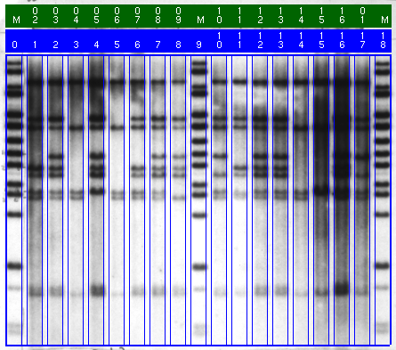
Figure 3.6: Image with lane boundaries, lane-index stripe and lane-label stripe.
The left and right boundaries of each of the lanes in the image are determined automatically. The number of lanes identified is based on the number of lanes defined in the gel-format file. After the program performs its automatic-detection process, which takes only a few seconds, you may accept the results or you may "edit" or adjust the lane boundaries. When you are finished, each lane is labeled.
- To add a lane boundary, depress MB1 in the vicinity of where you would like the boundary. A vertical line will appear that can be moved for precise placement. While MB1 is depressed, move the pointer to the exact location and release MB1. The new boundary is fixed. If you don't get it quite right, delete it with MB2 and add it again with MB1.
- When you have finished editing, click MB3.
- The other stripe, the lane-label stripe, contains the lane labels from the gel-format file. However, only the last 2 characters of each label are displayed. The lanes labeled "M" are marker lanes or size-standard lanes. On color displays, this stripe is green.
- The lane-index stripe and lane-label stripe may be moved or turned off. To the right of the image is a scrollbar. Above the scrollbar are 3 tiny colored buttons. The middle button (blue on color displays) is a 3-way toggle for the lane stripes. The 3 positions are "above" the image, "below" the image, and "off".
- If inheritance is active, a third stripe (inheritance stripe), containing family relationship codes, is treated as the other two stripes.

Figure 3.6: Image with lane boundaries, lane-index stripe and lane-label stripe.
Backward to Chapter 3, section 3.3
Forward to Chapter 3, section 3.5