Figure 3.7: The Template Edit Dialog.
After the lane boundaries have been delineated, you may identify the bands in the size-standard lanes. You will first allow the program to automatically detect what it can; then, you will edit the results so that the number of detected bands matches a pre-defined template. An example template, and the one used for image k102.avg, may be found in Appendix A.4. The purpose of the template is to have a standard against which images can be "warped" into alignment so as to have some basis of comparison with one another.

Figure 3.7: The Template Edit Dialog.
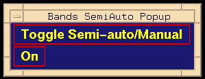
- Manual: when MB1 is clicked in a marker lane, a band is drawn at that location.
You may switch at any time you are editing and are encouraged to experiment with both options.

Figure 3.8: The Semi-automatic band-insertion toggle ("On" or "Off").
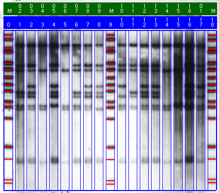
Figure 3.9 shows the superimposed band bars in the size-standard lanes.

Figure 3.9: The red band bars in the size-standard lanes indicate band detections.
Backward to Chapter 3, section 3.4
Forward to Chapter 3, section 3.6