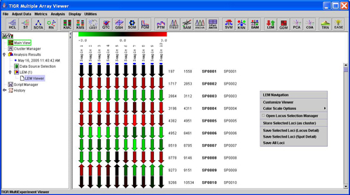
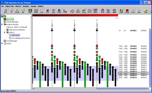
LEM viewer with fixed length locus arrows
The Linear Expression Map module produces a viewer to display locus level expression information organized by chromosomal location. The LEM aligns the sampled loci from multiple samples in a single viewer so that expression patterns for loci and groups of loci can be visualized. The expression values from all spots on the slide that map to a particular locus are averaged to produce a single value for a locus. The map is highly customizable in appearance and has fine and course navigational controls to assist in stepping through the genome or chromosome being viewed. The LEM features also include options to view locus detail, options to view locus related spot annotation information, and the option to link to web resources for additional information about a selected locus.
The LEM organizes loci by chromosomal location where loci are represented as arrows that indicate the direction of transcription. Initially, the LEM will be configured to have fixed locus arrow lengths and fixed length open areas between sampled loci. The header indicates the sample related to each column of loci on the map. The arrow colors represent the mean expression for the locus in the measured sample. The initial color representation takes the color from a gradient within the displayed range in the header. The annotation for each locus includes the 5’ location, the 3’ location, and the selected locus identifier. The last column is reserved for a user selected field of annotation that can be selected from the ‘Display’ menu of MeV (Please see manual section Selecting Gene Annotation).
– an annotation key that will map spots to loci.
-5’ and 3’ coordinates that correspond to the set of loci.
– an annotation key to indicate on which chromosome the loci is located. This information is not needed in the case of organisms that have only one chromosome.
The should be an annotation field loaded with the annotation during the expression file load in MeV. If the input data is in mev format then the locus identifier should be a field in the corresponding annotation (MeV .ann format file). For other formats this annotation should be found in the data file where each locus id is on the row corresponding to the associated spot information (annotation and expression data). (Please see the manual section: Loading Expression Data, for information on file loading for specific file format loading instructions).
In the case where chromosomal information is not supplied during the initial MeV file load, an auxiliary coordinate file can be supplied for LEM construction. The format of the file is a text tab-delimited format with a row for each locus. The columns have the following order ( [] indicates optional column):
The file should not have a header. Spots in the loaded data set will be ignored if they map to loci for which location information is incomplete or missing.
The initialization dialog collects information that indicates where the critical information for LEM construction resides and provides information about the nature of the data.
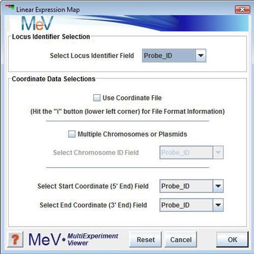
Locus Identifier Field
This option selects the annotation field that maps spots to loci.
Use Coordinate File
This option indicates if coordinate information will be loaded via an auxiliary coordinate file described above.
Multiple Chromosomes Option
This check box indicates if there are multiple chromosomes. If selected, MeV will expect chromosome identification information from the coordinate file or as a loaded annotation field in MeV. If the presence of multiple chromosomes or plasmids are indicated then there will be one map produced for each chromosome or plasmid.
The 5’ and 3’ annotation fields indicate which annotation fields in MeV identify the coordinate information if a coordinate file is not used.
Several features to help navigate over the LEM, to customize the appearance, and to extract information from the LEM are available via a right-click context menu. The following is a list of general features that are described in more detail in later sections. Most of these features correspond to menu options except for Locus Information Panels which are launched with a left mouse click on a locus arrow.
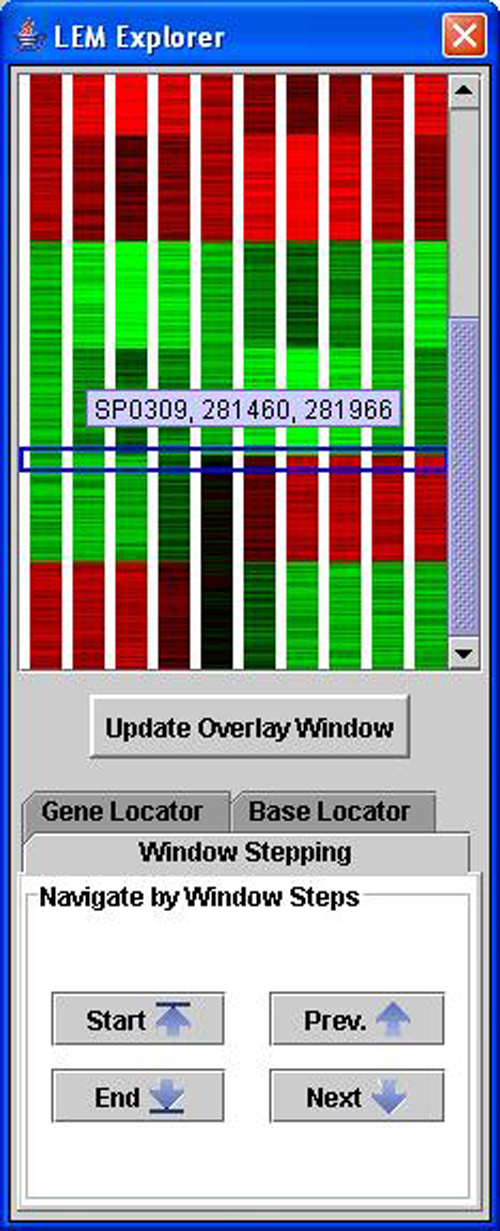
The LEM navigation controller is launched via the right-click menu option titled LEM Navigation. The Navigation Control provides several options for moving within the LEM. The upper section of the control is a reduced representation of the LEM where each locus is one pixel high. A blue rectangle indicates the area that is currently visible in MeV’s main window.
Click to Location
In this option the main view jumps to a location in the LEM that corresponds to the location of a left mouse click in the Navigation Controller’s LEM representation. The blue rectangle outline of the main viewer’s range is updated to reflect the current viewable location in the main viewer. Aside from clicking on obvious expression features, the reduced size navigation screen also displays a tool tip to indicate the locus id and location information for the element under the mouse tip. This feature allows one to mouse over the controller in search of a particular locus or base location. The reduced size view can be a quick means to take a survey of the genome or chromosome in the LEM.
Window Stepping
This option allows you to step through the LEM systematically by advancing by one view-screen at a time. During window stepping the blue rectangle will update to indicate the LEM location that is visible in the main viewer. The buttons to control this are located at the bottom of the controller under a tab labeled Window Stepping. Shortcuts to the start and end of the LEM are additional options to quickly jump to those end-points.
Gene Locator
This option moves the LEM to a selected Locus. The controls for this are under a tab in the controller labeled Gene Locator. Provide a locus identifier and the LEM will jump to that location with the indicated locus at the top of the viewer. This feature is useful when one has specific loci of interest.
Base Locator
This option moves the LEM to a specified base location. The controls are found under the Base Locator tab in the navigation control window. Entering a base location will move the main view to the locus or loci that cover the entered base location.
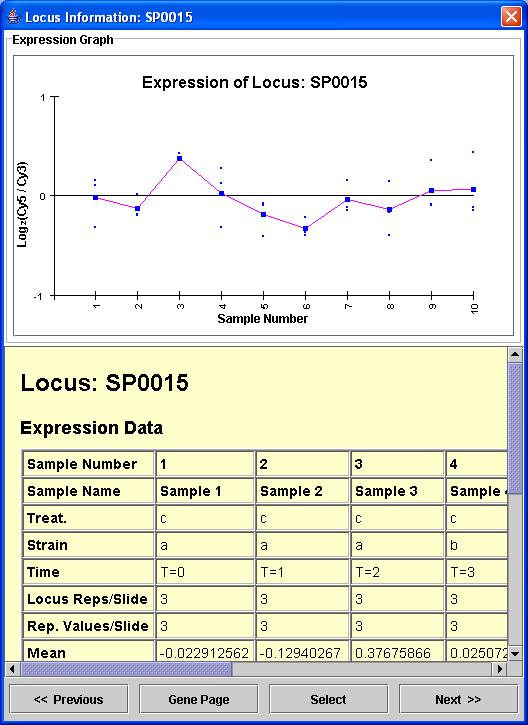
Locus information panels can be launched by a left mouse click on a locus arrow. The mean expression of a locus for each of the loaded samples is displayed in an expression graph. If there are several spots on the slide that correspond to the locus, each spot will be plotted as a point. The lower half of the panel has a table that contains expression information and another table that contains full annotation information for all spots associated with the locus.
The locus information window contains four buttons at the bottom. The and buttons update the information in the panel to correspond to the next or previous locus relative to the currently displayed locus. This feature allows one to advance one locus at a time in order to compare expression patterns between adjacent loci. This can allow the user to step through sections by viewing loci in order.
The button is used to push the locus onto the LEM’s locus selection list. The locus selection features are detailed in a later section.
The button launches a web resource relevant to the displayed locus. If the appropriate resource cannot be identified by MeV using the locus ID field name, a list of resources will be presented from which one can identify the proper resource.
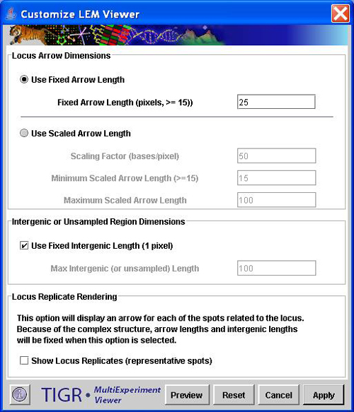
The LEM permits one to scale loci based sequence length so that the arrows corresponding to loci reflect the length of the sequence. User defined constraints allow one to limit the length to fall within reasonable bounds. The scaling options are available via the right click context menu by selecting the ‘Customize Viewer’ menu item. A single dialog box helps to define the view.
The main selection to make is whether the loci arrows should be of fixed length, in which case the user selects the fixed length in pixels, or if the arrow length should be scaled to reflect locus sequence length. If the loci arrows are scaled, a scaling factor can be selected to control resolution. Selecting fewer bases per pixel will elongate the viewer and will allow one to distinguish finer differences in length. The minimum arrow length is designed to render very small sequences with at least a small arrow so that associated annotation can be displayed. The maximum scaled arrow length allows one to constrain long sequences to a reasonable length. When using the scaled arrow lengths, loci that have overlapping coordinates are offset to the right so that arrows do not directly overlap.
When in the scaled locus mode the arrows have an ‘anchor’ point to aid in locus selection. If you mouse over the anchor point, the locus will be highlighted and the anchor point will change from white to red. A shift-left mouse click will select the locus. Another special feature in this mode is that locus annotation that overlaps due to locus overlap will be rendered with the policy of highlighted locus annotation on top.
The un-sampled areas of the chromosome have a separate set of scaling controls. The base to pixel conversion factor is used if these areas are scaled. If these areas are scaled then a maximum length can be selected so that large areas without sampled loci are not extremely long. This prevents the occurrence of long areas without expression values.
Note that during interaction with this dialog one can hit the preview button to view the alterations to the LEM. If cancel is hit, the dialog box will be dismissed and the original settings will be restored to the LEM. The reset button will not dismiss the dialog but will return the values to the values of the LEM at the time the dialog was launched.
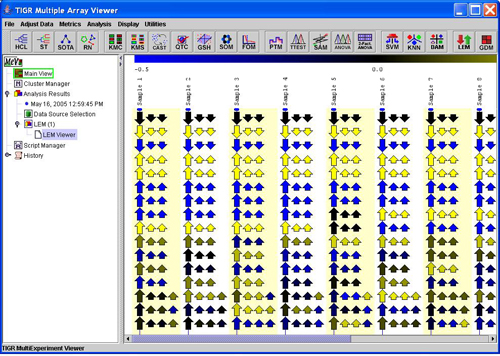
The last option on the Customization dialog is the option to expand the viewer to show an arrow for each spot related to a loci. If this is selected the arrow that represents the mean expression for a locus is displayed as usual but in addition arrows are displayed that correspond to each spot related to the locus. This displays the expression of the spots that contribute to the locus mean. The additional arrows for locus spots are displayed to the right of the locus mean arrow and are shortened slightly to help differentiate. The background of alternate samples is shaded lightly to help distinguish sample boundaries. When this option is selected, the arrow lengths and open areas are fixed to simplify the view so that spot level arrows are not confused with short loci arrows.
The arrows in the LEM are given a color that indicates the level of expression. This color is taken from a scale based on the spot’s expression value. Altering the color scale limits can help resolve (or ignore if appropriate) levels of expression that are closer together. The LEM provides three modes to assign colors to expression values. These color assignment modes can be selected via the right click menu in a submenu labeled .
Gradient Color Mode
The gradient option is commonly used and the value limits can be set using MeV’s ‘Display’ menu. The Display menu also contains options to apply a different gradient color scheme. The Gradient limits and color scheme options are described in other manual sections related to the Display menu. These controls are placed in MeV’s menu since they relate to all expression views in MeV. (Please see manual sections, Setting Color Scale Limits, and Color Scheme Selection for information on setting the limits when using the gradient color mode).
Three Bin Mode
In the three bin color mode, colors are assigned from one of three expression bins. The user sets a high and a low limit on expression and values exceeding these limits are given a color that corresponds to the appropriate bin or left empty if the expression value falls within the set cutoffs.
Five Bin Mode
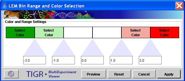
The five bin mode provides four cutoffs levels and while the LEM still colors the arrows with discrete colors, the two extra bins allow for an intermediate high and low expression bins.
Setting Limits and Colors for the Bin Modes
The discrete color bin modes have cutoff values and color selection options contained in a dialog that can be launched via a right click menu option labeled Bin Colors and Limits. The dialog has colored buttons that can be clicked to display a palette for color selection. Five cutoffs for the bins can be altered via text fields. In the case of the three bin mode only the outer most limits and colors are used. The values of the bins should increase from left to right. This convention is enforced to maintain valid limits when switching between 3 bin and 5 bin modes. Note that the preview button will apply the current settings to the LEM. To revert back to the original settings, use Reset and then Preview or Apply.
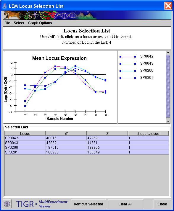
The LEM viewer allows the user to select loci of interest. These loci can be output to file in various formats and can be stored as an MeV cluster in the cluster manager/repository. A shift-left-click on a locus will add the locus to the selection list. one can shift-left-click again on the locus to deselect the locus and remove it from the list. Selected loci will have a red marker to the left of the locus arrow and will have its annotation shaded in red.
The locus selection list can be viewed by selecting the Locus Selection List option from the right click menu in the LEM. The selection list has buttons that allow one to clear selected loci or to clear all loci from the list. The file menu on the selection list provides options to save all loci or selected loci to tab delimited text files that can be loaded into MeV or can be opened in a spreadsheet. These options are similar to options from the main LEM right click menu and will be discussed in detail. The Select menu has options to make targeted selections of loci by either selecting a locus or by specification of a base location range. The Graph Options menu has options to control locus expression graph rendering. One option is used to hide or show the locus graph while the other option is used to display the graph as either a simple monochrome graph or to render each locus graph as a different color as indicated by the key.
The locus selection graph updates to show the graphs for the loci that are selected in the table section of the window. Using a shift or control click in the table will permit the selection of multiple rows in the table and will overlay the expression graphs of all selected loci.
MeV’s cluster manager contains many cluster set utilities and cluster operations such as unions and intersections. Loci that are of interest can be stored as a cluster in the manager by selecting the Store Cluster option from the LEM right click menu. As usual the user will be prompted to assign an optional label and description to the cluster and will be prompted for a color to associate with the elements of the cluster so they can be tracked during analysis. When storing a set of loci to a cluster, the elements of the cluster are actually the spots on the slide that map to the set of loci. If multiple spots are associated with a locus in the selection list, each of these related spots are elements in the formed cluster. (Please see section 8 in the manual, Working with Clusters, to learn more about the options within the cluster manager.)
These options output selected loci or all loci to a text tab delimited file. In all cases the files are in the TDMS (tab delimited multiple sample) format and ready for import into MeV as independent data sets. The TDMS format is described in the appendix on file formats.
Save Selected Loci (Locus Detail)
This options saves locus level information to a TDMS file which contains locus identifier, chromosome (if more than one exists), and locus coordinate information. The expression value for each locus is a mean expression value for all spots related to the locus.
Save Selected Loci (Spot Detail)
This option saves spot values for spots related to selected loci. All annotation for the spots is output to the TDMS format file.
Save All Loci
This option provides the output described in the Save Selected Loci (Locus Detail) option described above except that it extends to include all identified loci in the viewer.
The LEM module produces three additional viewers. 1.) Linear Expression Graph Viewers, 2.) Table of Unmapped Spots and, 3.) Locus Mapping Summary.
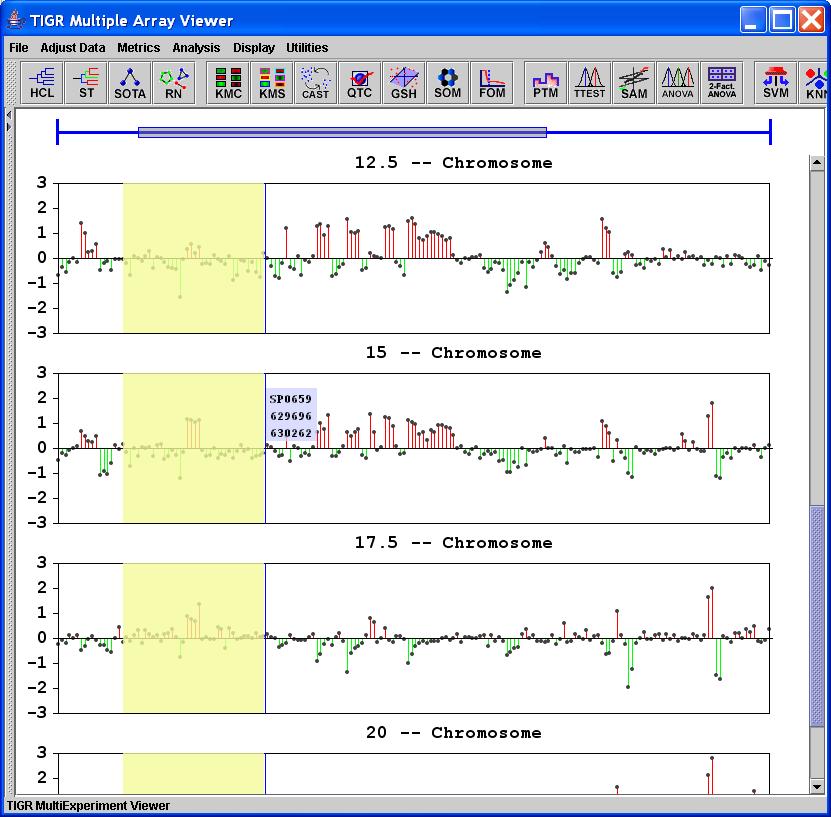
Linear Expression Graphs (LEGs) are also produced during LEM execution. These graphs depict gene expression as a graph where features are segregated by chromosome or plasmid and then ordered based on chromosomal location. The LEG Viewer node is appended to the result tree just below the node for the LEM viewer.
A right click context menu allows several options for customizing the view. The following sections describe these basic features.
Viewer Modes
:The default view for the LEG Viewer, Tiled View, produces a set of graphs, one for each sample that are stacked vertically. A click-drag of the mouse allows you to zoom in on a section of the graph. The header bar will update to indicate zoom level and the current location on the graph. The default color scheme produces 35 unique marker/line color combinations.
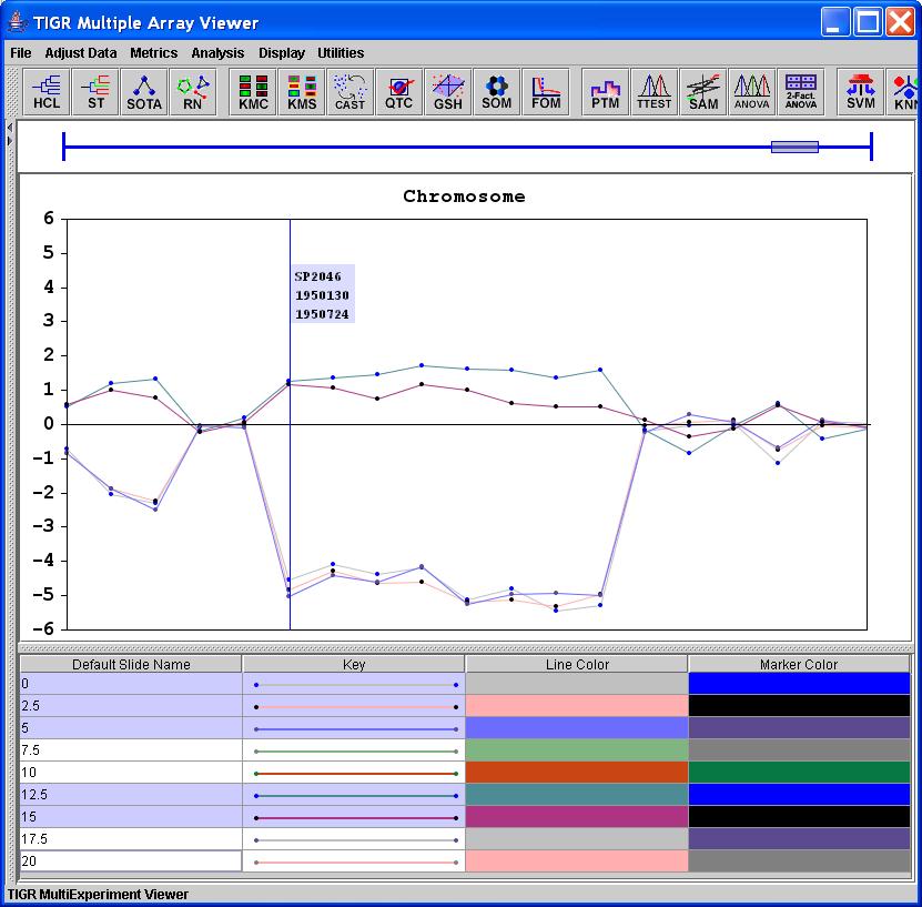
:The overlay view displays a single graph over which one or more samples can be graphed. The click-drag zoom option is still enabled in this mode. A ctrl-click in the table will permit multiple selections in the table. Clicking on the marker or line colors in the table will permit customization of the color representation for that sample’s graph. In practice, the overlay mode is most practical for viewing a few samples at a time and it is often useful to zoom in on particular regions of interest
Below viewer mode in the right-click menu there is a customize graph option which allows the y-axis range to be set as well as providing other graph rendering options.
Two options are enabled to permit y scaling. The initial default setting retrieves the range from the color scale range in MeV’s display menu. A custom range option with tick interval provides a greater level of control.
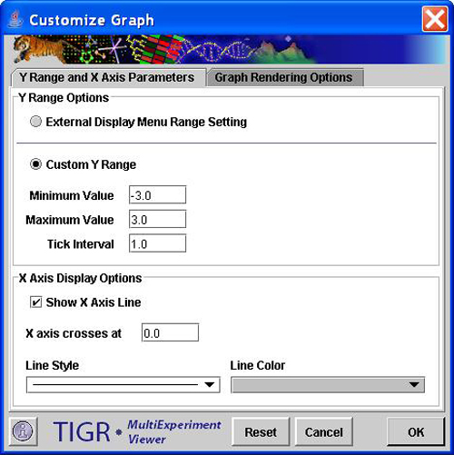
An optional x axis line can be drawn at a specified y value. This can be a good reference line when dealing with log ratio data. Formatting options include selectable line style and color.
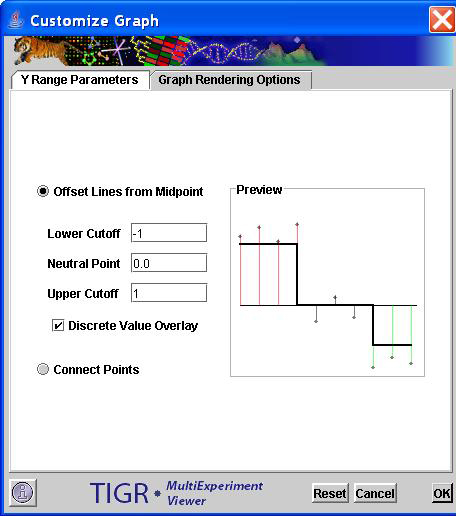
The second panel of the Customization Dialog includes two major graph rendering options. The Offset Lines from Midpoint mode draws points for expression values and connects those with a neutral line or baseline value. The cutoff values allow one to set limits which affect the color scheme of the offset lines. All points above the upper cutoff have red lines to the baseline, while points below the lower cutoff have green connecting lines. Points that fall within the cutoffs have black connecting lines.
The other option is to render the graph using lines to connect points. When viewing the graph in overlay mode this is the default setting so that the various samples can be easily identified.
The last rendering option is to use a discrete value overlay. This option uses the supplied cutoff values and overlays the graph with a square wave pattern where points exceeding the limits force the line through the appropriate limit. This overlay, shown in the preview mode in the dialog figure, can help to visually identify regions of contiguous, at least in ordering, genes that show similar behavior.
The final two menu options in the Graph Viewer include an option to display a locus reference line that provides gene identifier and location information as you mouse over the graph and an option to reset the x range to zoom out to show all data in one window.
In the event that there are control spots on the slide or spots for which the loci and coordinate information is not known, a table is created to collect and identify these spots. This table lists all annotation for unmapped spots and can be reviewed, searched, or saved to confirm that the listed spots are indeed unmapped and cannot contribute to the LEM. The table has the properties and options of MeV’s cluster table viewers that are described in the manual.
The mapping summary is placed on MeV’s result navigation tree below the unmapped spot table, if present, and the LEM viewer(s). This viewer list information about the number of spots that are entering LEM, the number of spots that map to loci, the fraction of spots that are mapped, and lists all of the parameters selected when producing the LEM. If the LEM doesn’t appear to render loci appropriately, check the parameter listing to confirm that the proper coordinate information was supplied and other parameters such as the indication of multiple chromosomes or plasmids was indicated correctly. In addition to global mapping data, the number of mapped loci and the number of spots that correspond to each chromosome or plasmid are listed.